RACK >> SUB-RACK >> SUB-UNIT >> Panels
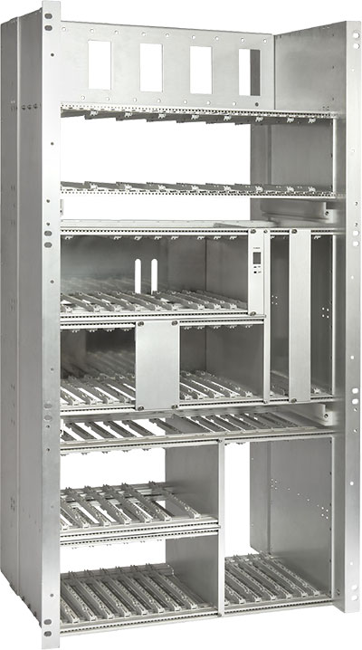 RACK:The 19-inch rack mounting system was first presented in 1970 at the Hannover Fair by AEG Telefunken and has since become the undisputed mechanical standard for all industrial applications.
On this site you will find a wide assortment of modular storage systems for electronics with different solutions for setting up 19" floor equipment (rack cabinets), desk or tortabili (rack containers) to hang wall or pole, and many other special ones.
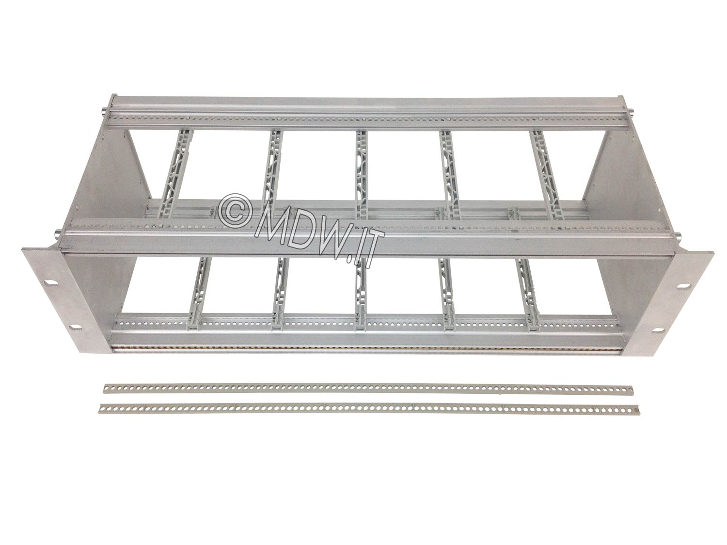
SUB-RACK: Objects mounted inside a RACK are called EuroRack or SUBRACK. The subracks have standardized dimensions, the height is measured in rack units and the most common models are those 3, 6 and 9 units high, the external width is 19" (the side flanges allow them to be fixed inside a rack), for all internal measurements see section https://subrack.eu/423-subrack.
Our offer of subracks is divided into "Silver Series", "Gold Series" and "Platinum Series", each family includes a wide range of accessories and customizations able to cover all needs and types of applications:
Full shielded subracks certified for railway applications
, IEC-60297-3-103)
Custom subracks from 3 to 18 units of different depths
In the Silver Series, the 19" profiles (front and rear crosspieces) are fixed to the walls using a screw with M5 thread. In the Gold Series we find two screws with M4 threads that guarantee greater rigidity. Even greater solidity is offered by the 2000 series, which lends itself both to mounting on 19" racks and as a table container, with a structure complemented by upper and lower covers in plasticized galvanized steel sheet with EMC shielding properties.
Subracks are made according to DIN 41494 and manufactured for the use of connectors in accordance with DIN 41612, DIN 41617, MIL-C-21097 and later. The surface protection of the aluminum elements is standard chrome-plated shielding "CEPIDINE 3000", which has the same paperwork as the ALODINE 1000, but is more manipulable without leaving traces and unsightly imprints. On request, the natural or colored anodizing treatment is carried out.
The side walls can be made of extruded which has already integrated the flanges for 19" mounting into the structure. However, in applications where greater subrack depth is required, aluminium plate side walls can be used. In the latter case the basket is finished with a rear closing bracket and a front flange for fixing.
Subracks (or module rack drawers) have standardized dimensions, height is measured in rack unit, outer width of subracks is 19" including cabinet mounting flanges, or less when used in contexts other than the system 19" or as torted chassies (desk).
Internally, the width of the subracks is specified by the TE unit (Teilungseinheiten = splitting unit) or HP (Horizontal Pitch), where 1 HP equals 0.20 inches (5.08 mm).
The most popular subracks today are 3U, 6U or multiples of them.
Subracks can contain printed circuit boards and subunit enclosures that can be 100 mm high (3U subrack) or 233.4 mm (6U subrack) with the different depths indicated in the table:
The subracks are made according to DIN 41494 and are designed for the use of connectors according to DIN 41612, DIN 41617, MIL-C-21097.Material: aluminum thickness 2 mm.
The surface protection of the aluminum elements is standard chromed shielding, on request the natural or colored anodizing treatment is realized.
Board subracks with direct insertion or backplane connectors, model with 19" flange integrated in the side (maximum depth P=280)
|
|||
 |
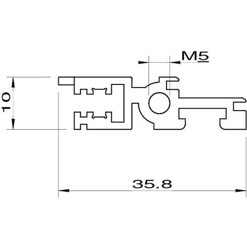 Front profile with single M5 threaded fixing hole |
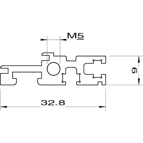 Flat rear profile for backplane subracks |
 Extruded aluminium sidewall with built-in 19" flange |
Board subracks with direct insertion or backplane connectors, Model with flat sides plus flange 19" (achievable of any depth) |
||||
 |
 Profilo anteriore con singolo foro di fissaggio filettato M5 |
 Flat rear profile for backplane subrack |
 Flat aluminium sidewall |
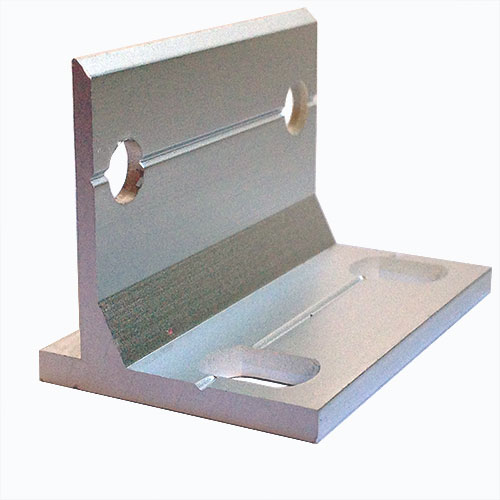 Flange 19" in extruded aluminium |
Board subracks with 90 mm mounting centre distance connectors according to DIN 41612, IEC 60603-2, EN 60603-2, model with 19" flange integrated in the side (maximum depth P=280) |
|||
 |
 Front profile with single threaded fixing hole M5 |
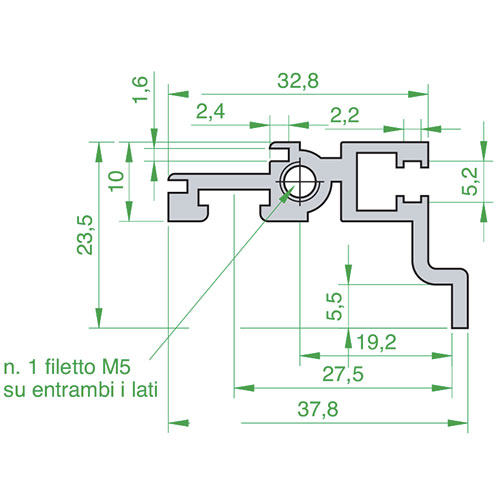 Back profile for boards with 90 mm mounting centre distance connectors |
 Extruded aluminium side wall with built-in 19" flange |
Board subracks with 90 mm mounting centre distance connectors according to DIN 41612, IEC 60603-2, EN 60603-2, Model with flat sides plus flange 19" (achievable of any depth) |
||||
 |
 Front profile with single threaded fixing hole M5 |
 Back profile for boards with 90 mm mounting centre distance connectors |
 Flat aluminium sidewall |
 Flange 19" in extruded aluminium |
SUB-UNIT: Inside the SUBRACKS mechanical and electronic components can be mounted directly on PCBs fixed to the subrack, or by means of printed circuits in eurocard or double eurocard form inserted on guides that allow housing and removal vertically, or by mechanical containers that exploit these guides to create a sort of removable drawer system (the SUB-UINT). Our technical department has several decades of experience in the development of accessories and solutions for sub-racks and sub-units. We are therefore able to provide pre and post sales advice on a wide range of solutions for edge-socket connector connectivity even for those particularly hostile environments where there are considerable stresses and vibrations (railway, naval, aerospace).
 The drawer subunits have been designed for the use of components to be mechanically protected, shielded and supported heavy weights.
• Can be inserted in all "Silver", "Gold", "Platinum" series subracks.
• The printed circuit boards can be inserted both to the right and to the left of the subunit, if desired, using the appropriate guides, also in the center
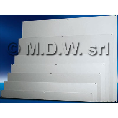
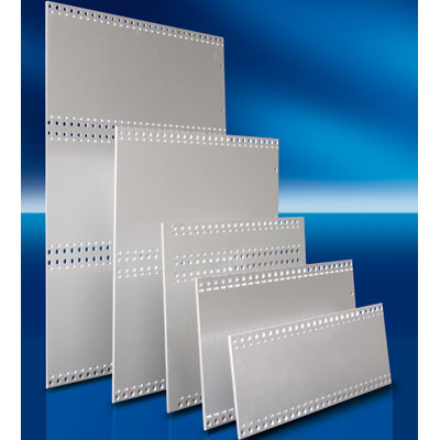
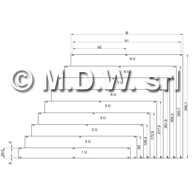 Blind front panels for subracks, complete with 3.3 x 5.9 mm slots to house plastic or metal sleeves for screws, or inserts for quick locks. Material: aluminum, plexiglass, steel. Thickness: 2 - 2,5 - 3 mm Processing: graphic and mechanical processes of all kinds are possible, aluminum panels can be treated in different ways for different needs, they can be anodized or conductive (EMC), equipped with fingher, painted. The fronts are then completed with handles, extractors / inserters, penthouses for cards.
Panel dimensions: the dimensions of the closing front panels are defined in height by the number of rack units (U RU), and in width by the number of TE (HP)
| (U) / mm | TE width (HP) | dimension B (mm) | dimension b1 (mm) | dimension b2 (mm) | code (anodized) |
| 1 / 39,5 | 42 | 213 | 198,1 | - | FCC 1-42T |
| 1 / 39,5 | 84 | 426,4 | 411,5 | 203,2 | FCC 1-84T |
| 2 / 84 | 42 | 213 | 198,1 | - | FCC 2-42T |
| 2 / 84 | 60 | 304,5 | 289,6 | 147,3 | FCC 2-60T |
| 2 / 84 | 84 | 426,4 | 411,5 | 203,2 | FCC 2-84T |
| 3 / 128.4 | 1 | 5 | - | - | FCC 3-01T |
| 3 / 128,4 | 2 | 9,8 | - | - | FCC 3-02T |
| 3 / 128.4 | 3 | 14.9 | - | - | FCC 3-03T |
| 3 / 128,4 | 4 | 20 | - | - | FCC 3-04T |
| 3 / 128.4 | 5 | 25.1 | - | - | FCC 3-05T |
| 3 / 128,4 | 6 | 30,1 | 15,2 | - | FCC 3-06T |
| 3 / 128.4 | 7 | 35.3 | 20.3 | - | FCC 3-07T |
| 3 / 128,4 | 8 | 40,3 | 25,4 | - | FCC 3-08T |
| 3 / 128.4 | 9 | 45.4 | 30.5 | - | FCC 3-09T |
| 3 / 128,4 | 10 | 50,5 | 35,6 | - | FCC 3-10T |
| 3 / 128.4 | 12 | 60.6 | 45.7 | - | FCC 3-12T |
| 3 / 128,4 | 14 | 70,8 | 55,9 | - | FCC 3-14T |
| 3 / 128.4 | 15 | 75.9 | 61st | - | FCC 3-15T |
| 3 / 128,4 | 16 | 80,9 | 66,1 | - | FCC 3-16T |
| 3 / 128.4 | 17th | 86th | 71.1 | - | FCC 3-17T |
| 3 / 128,4 | 18 | 91,1 | 76,2 | - | FCC 3-18T |
| 3 / 128.4 | 20 | 101.3 | 86.4 | - | FCC 3-20T |
| 3 / 128,4 | 21 | 106,3 | 91,4 | - | FCC 3-21T |
| 3 / 128.4 | 22nd | 111.4 | 96.5 | - | FCC 3-22T |
| 3 / 128,4 | 26 | 131,8 | 116,9 | - | FCC 3-26T |
| 3 / 128.4 | 27th | 136.8 | 121.9 | - | FCC 3-27T |
| 3 / 128,4 | 28 | 141,9 | 127 | - | FCC 3-28T |
| 3 / 128.4 | 29th | 147th | 132.1 | - | FCC 3-29T |
| 3 / 128,4 | 30 | 152,1 | 137,2 | - | FCC 3-30T |
| 3 / 128.4 | 32nd | 162.2 | 147.3 | - | FCC 3-32T |
| 3 / 128,4 | 38 | 192,7 | 177,8 | - | FCC 3-38T |
| 3 / 128.4 | 39th | 197.8 | 182.9 | - | FCC 3-39T |
| 3 / 128,4 | 40 | 202,9 | 188 | - | FCC 3-40T |
| 3 / 128.4 | 41st | 207.9 | 193rd | - | FCC 3-41T |
| 3 / 128,4 | 42 | 213 | 198,1 | - | FCC 3-42T |
| 3 / 128.4 | 48th | 243.5 | 228.6 | - | FCC 3-48T |
| 3 / 128,4 | 50 | 254 | 239,1 | - | FCC 3-50T |
| 3 / 128.4 | 60th | 304.5 | 289.6 | 147.3 | FCC 3-60T |
| 3 / 128,4 | 61 | 309,5 | 294,9 | 147,3 | FCC 3-61T |
| 3 / 128.4 | 63rd | 319.7 | 304.8 | 147.3 | FCC 3-63T |
| 3 / 128,4 | 76 | 385,8 | 370,9 | 177,8 | FCC 3-76T |
| 3 / 128.4 | 81st | 411.1 | 396.2 | 198.1 | FCC 3-81T |
| 3 / 128,4 | 84 | 426,4 | 411,5 | 203,2 | FCC 3-84T |
subrack.eu + armadi-rack.it© are run by M.D.W. srl - About Us
M.D.W. srl Chamber of Commerce, Bologna
REA n° 465866
PI/CF 02766841205
Legal office:Piazza Minghetti, 4/D
Bologna 40124 BO, Italy
Operating office:Via Edmondo De Amicis 7
Casalecchio di Reno 40033 BO, Italy