
 Login
Login Cart
Cart Wish Lists



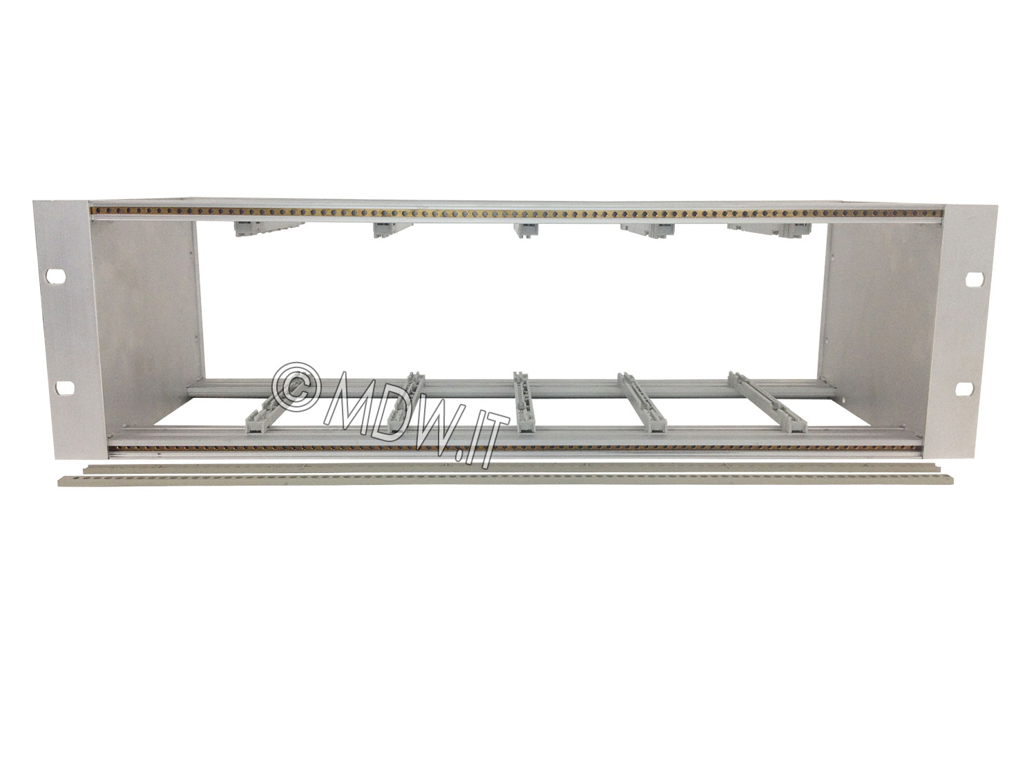
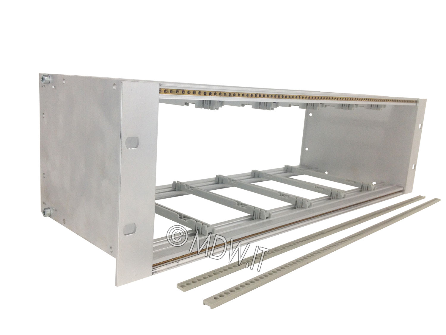
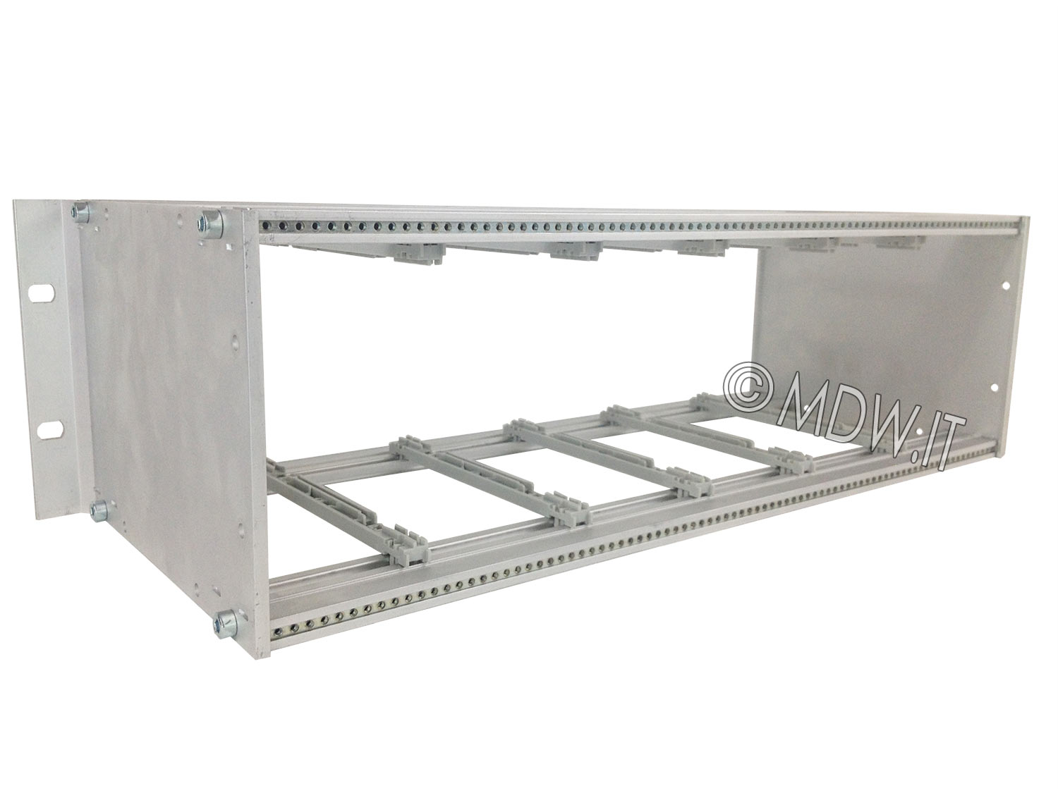
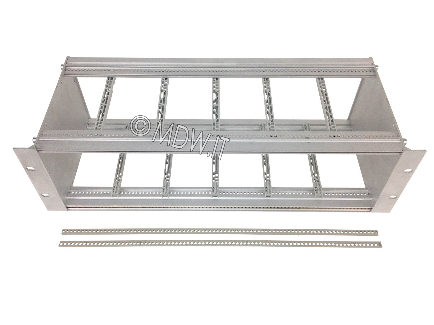
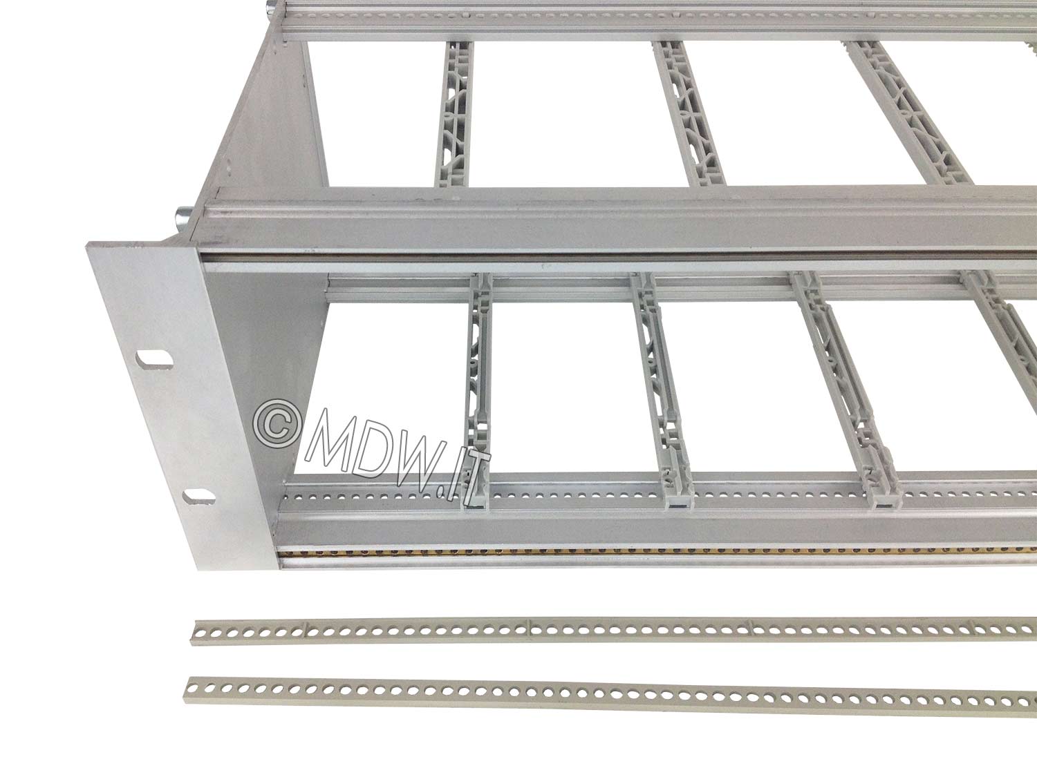
Subracks for modules made following the requirements of the DIN 41494 and IEC 60297-3 standards for subunits or electrical boards in Eurocard (Europe) format or larger with direct insertion or backplane connectors.
They are suitable for mounting backplanes (Mother boards) with the application of various types of connectors or for the use of direct insertion connectors of the MIL - C - 21097 type.
These subracks are made with one-piece extruded aluminum side walls that incorporate the mounting flange for 19” rack structures. The front, rear and median profiles (where present) have a single M5 threaded fixing hole.
The side walls and support profiles are surface treated as standard with cepidine 1000 (a conductive and EMC surface treatment that improves the corrosion resistance of the aluminium without altering its electrical characteristics).
Natural or colored anodizing, or other aluminum treatments, can be provided upon request.
The basic supply composition, parts and quantities, is shown in the table and includes a minimum number of card guides of appropriate length.
The material is supplied in assembly kits.
Material: 2 mm thick aluminum
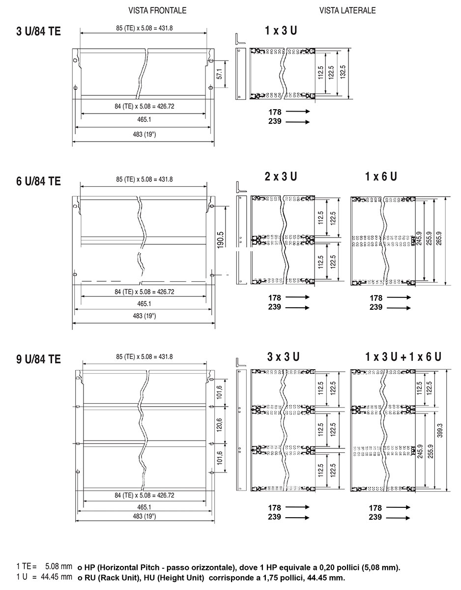
Synoptic table of the subrack family
Subracks for backplanes with single hole M5 profiles | supply composition and quantity of individual parts Click on the table to open the technical data sheets | |||||||||
Number of units | Depth | Code | PL | PA | PP | PM | B | THERE | LF | GS |
1 x 3U | 178 239 | |||||||||
1 x 6U | 178 239 | |||||||||
2 x 3U | 178 239 | |||||||||
1 x 9U | 178 239 | |||||||||
1 x 3U + 1 x 6U | 178 239 | |||||||||
3 x 3U | 178 239 | |||||||||
Legend:
PL = Side wall
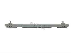
PA = Front profile
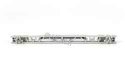
PP = Rear profile
PM = Median profile
B = Allen screw M 5 x 12
LI = Insulating strip
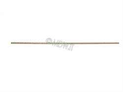
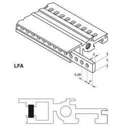
LF = Threaded strip M 2.5
GS = Card Guide
To be ordered separately:
GA = Protective grille
CP = Protective Hood
PD = Component support plane
LF= Threaded strip M 2.5 or M 3
LD = Conductive spacer strip
PPR = Lowered rear profile for use of boards with a depth lower than standard
BZ = Z-bars (for direct fixing of special connectors)
 Versions
 PDF data sheet